Exploring Chunky Graphics: A New 3-Color Screen Mode for ZX81
Exploring my version of a new ZX81 graphics mode and the technical details behind it.
Out on a run back in November of last year, I had this idea to create a 3-color screen mode of the ZX81. The idea was to use the checkered, or gray, graphic characters to add a third color. After reading about the C64 color modes, I called it chunky graphics as an homage to its wide pixel format. The pixel’s are chunky due to the 2x1 ratio and not being square. Let’s dig into the details.
# The seeds of an idea.
Of course, I‘d been using the different checkered graphics for a long time. The ZX81 doesn’t have graphics modes since it uses a character graphics display. But commands, like PLOT and UNPLOT work using the 4 pixel quadrants. This gives the ZX81 a resolution of 64x44, or 48 if using the last 2 lines. Using PRINT AT you can use any character the ZX81 can display.
Inspired, as noted in the introduction, by reading again about the Commodore 64’s graphics modes, I wondered if I could create something akin to a 3-color mode using the checkered characters. This would give me a 32x48 effective resolution when using the entire screen. I lose half the X resolution. But, I gain the ability to display 3 colors: black, white, and checkered. I’ll often refer to the checkered as hash or gray as well.
# Figuring out the math.
With the idea in mind, I started to work out the best algorithm. I knew this would be in assembly as I’d been hacking at graphics there already. To begin with, I wrote down all the graphics characters I would need to display:
00 - upper white, lower white
03 - upper black, lower white
08 - upper hash, lower hash
09 - upper white, lower hash
0A - upper hash, lower white
80 - upper black, lower black
83 - upper white, lower black
88 - upper hash, lower hash (inverted)
89 - upper black, lower hash (inverted)
8A - upper hash, lower black (inverted)
This gives me 10 graphic characters. Note that the bottom are technical inverted versions of the first 5. The checkered or hash character is also inverted, which is a bit annoying as they won't line up quite right. let's right that out in binary:
00000000 - upper white, lower white - 00
00000011 - upper black, lower white = 03
00001000 - upper hash, lower hash = 08
00001001 - upper white, lower hash = 09
00001010 - upper hash, lower white = 0A
10000000 - upper black, lower black= 80
10000011 - upper white, lower black = 83
10001000 - upper hash, lower hash = 88 (inverted)
10001001 - upper black, lower hash = 89 (inverted)
10001010 - upper hash, lower black = 8A (inverted)
Now, what I wanted to do was replicate the plot command but using a pen color. If I needed to convert the upper part of the character black, I would have the following options to go through:
00000011 - Upper black, lower white = 03
10000000 - Upper black, lower black= 80
10001001 - Upper black, lower hash = 89 (inverted hash)
This makes the program grow quite complex. This adds at least 3 comparisons for each of the colors in the bottom half of the character. That brute force approach would work, but would be needlessly complex and long. I needed something more compact and faster.
# Taking a different approach.
At first, I didn’t think there was any easy way to condense this. At least not using the approach I was taking above. Taking some time to do something else, I headed out on my Thanksgiving Run. Did about 6 miles and, as fate would have it, worked out the routine on my run. The best approach I came up with was this:
- Run a compare to convert to a standard format of two bits for top and two bits for bottom (basically a nibble).
- Then test if odd or even (bottom or top).
- Based on that put the pen color in top or bottom.
- Then use a table to convert to the real character and print it.
Sitting down to code, I determined I could use the same table for both conversions. Once to convert the onscreen character to an internal 4 bit (nibble) representation. And again to convert it back. The table needed to be in the correct order for my calculations.
        ; Here is the conversion table to the characters:
cp_char_table:
        db %00000000 ;  0 - 00000000 - white/white      00
        db %00001001 ;  1 - 00000001 - white/hash       09
        db %10000011 ;  2 - 00000010 - white/black      83
        db %11111111 ;  3 - 00000011 - not used
        db %00001010 ;  4 - 00000100 - hash/white       0A
        db %00001000 ;  5 - 00000101 - hash/hash        08
        db %10001010 ;  6 - 00000110 - hash/black       8A (inverted hash)
        db %11111111 ;  7 - 00000111 - not used
        db %00000011 ;  8 - 00001000 - black/white      03
        db %10001001 ;  9 - 00001001 - black/hash       89 (inverted hash)
        db %10000000 ; 10 - 00001010 - black/black      80
This table takes up 10 bytes and makes the rest of the code much simpler. To convert the on-screen character, I can through the table until I find it. Decrementing a counter, the program walks the table to find the right character.
        ; find char and convert to 4 bit normlized format
        ld hl,cp_char_table+10          ; start at end of table
        ld b,10                         ; walk backwards
cp_find_new_char_loop:
        cp (hl)                         ; did we match?
        jr z,cp_get_top_or_bottom       ; yes, skip ahead!
        dec hl                          ; try next character
        djnz cp_find_new_char_loop      ; no? Keep searching
One advantage of this code is that if you plot over a letter, it will treat it as a space (B will be zero). This is also the slowest part of the code as it has to scan the table. It is also non-deterministic as the timing will change based on where the character is in the table. Fortunately, we are only talking at most 10 comparisons at most. In practice, this is much faster than other options.
# Plotting the new color.
The next step in the process is to change the actual color. That requires a few different routines. None too difficult. The first is to determine if we are plotting in the upper or lower part of the character. The easiest way to do that is to see if the Y position is even or odd.
cp_get_top_or_bottom:
        ld a,(pen_color)
        ld d,a                          ; grab and set pen color

        ; d = pen color
        ; b = normalized char
        ; c = y coordinate

        ld a,c          ; get y coord
        rrca            ; check if even or odd
        jp nc,cp_is_even
For each branch, I then mask out that section and add in the pen color. For reference, the pen can be: 0 or white, 1 or hash, 2 or black. In binary this is 00, 01, and 10. The following code sets that values. The positive of this approach is I can use very simple math along with some register shifts.
cp_is_odd:
        ld a,%00001100  ; mask out bottom
        and b
        add a,d         ; add in pen color
        jp cp_print_char

cp_is_even:
        ld a,%00000011  ; mask out top
        and b
        sla d           ; shift pen color to top
        sla d
        add a,d         ; add in pen color
# Converting it back.
To convert from the internal representation to the actual character is quite simple. I only have to add the nibble to the table location. The routine looks more complex than it is. This is due to needing to convert the 8-bit register to the 16-bit memory address.
cp_print_char:
        ; a = new character
        ld l,a          ; extend to 16 bits
        ld h,0
        ld bc,cp_char_table
        add hl,bc       ; get destination
        ld a,(hl)       ; and grab new character

        pop hl          ; restore screen location
        ld (hl),a       ; load new character to screen

        ret             ; and done!
After re-using some code to grab the on-screen character, I had a functioning plot routine. The code is portable and should be easy to add into other programs.
# Doing something with it.
To test out the routine, I grabbed my line and circle routines from previous programs and converted them to use the chunky plot routine. This required me add in pen colors, but after a fixing a few math errors I had a working demo. It plots a few points, a circle and lines, and then starts printing a rotating line. I made it loop through the 3 shades (white, gray, black). It is pretty cool and very happy with it now.
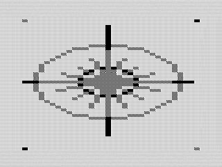 Chunky Plot, 2022 by Steven Reid
With the routine done, I started to think about where else I could use it. I have the perfect program. My old flight simulator used the gray characters to print the horizon. I could rewrite that program to use the line drawing routine with my chunky plot. Given that was a BASIC program, moving to assembly would speed things up. Not only would that make the program more playable, but would let me try out some other ideas.
As a side note, I learned through one of the ZX81 forums that a version of this was in one of the libraries for z88dk. Curious, I dug into that program to see what they did. To my surprise, it took the same approach. The table was reversed and there was minor math differences, but the routine was otherwise the same. Glad to see I wasn’t completely out in left field.